Five connected product tracks, with a separate modular-construction explainer. Step through each mechanism, compare its architecture and inspect the source references.
Select a technology below Five stages · optional spoken captions
Examine the original CAD assembly and patent-referenced mechanisms from every angle.
Joined span sections · schematic preview Open the interactive model to see the structure and pitch joint.
06Construction / Transport / Assembly
Modular blade construction
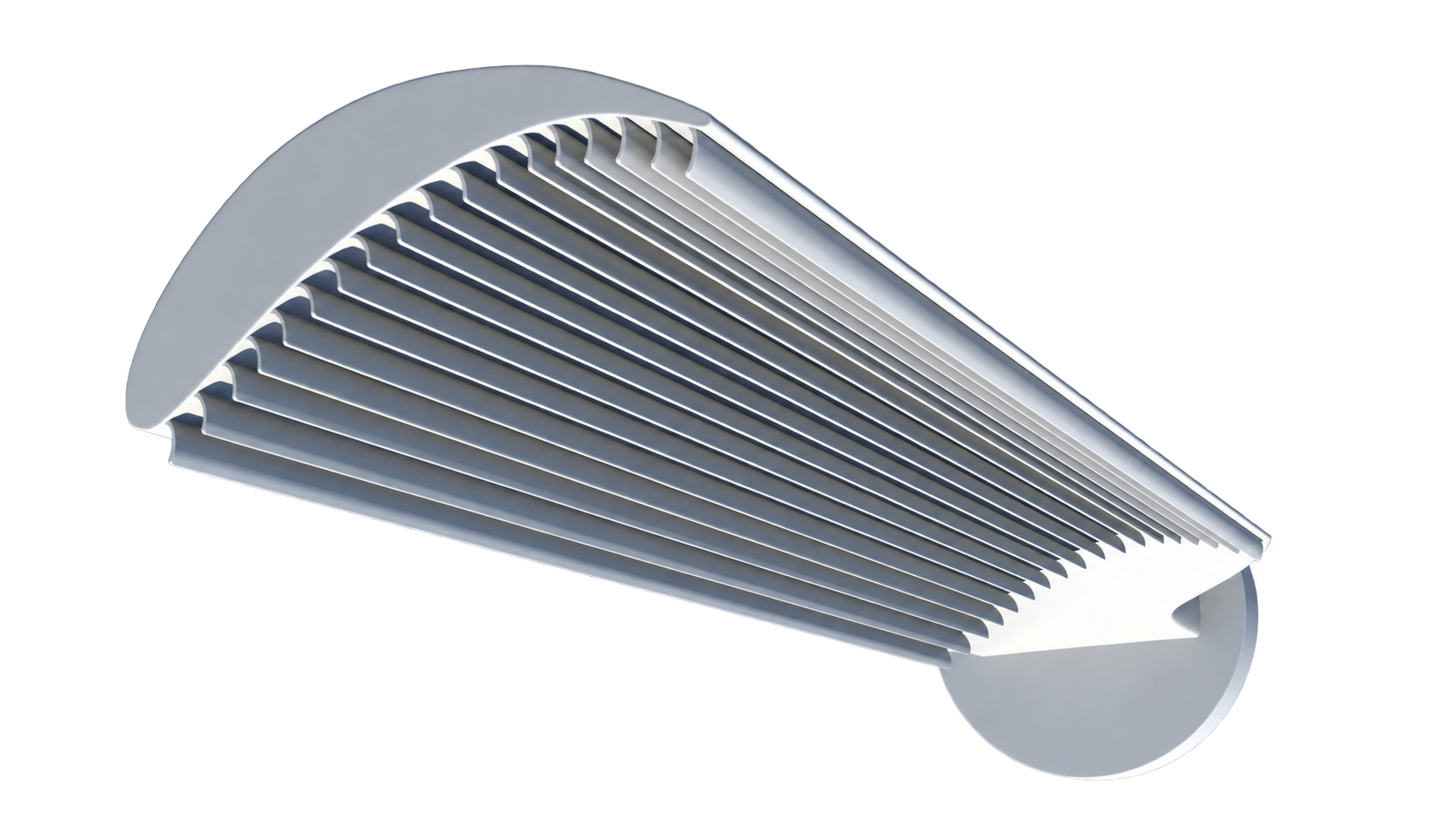
A smooth aerodynamic exterior assembled from joined span modules. This construction approach is distinct from surface fins and the optional internal weight mechanism.
The intended advantage
Transport manageable sections and assemble the blade near the site. The aim is to make installation accessible where a single very long blade would be difficult to move.
What we will establish
Joint strength, fatigue life, surface continuity, shipping envelopes, assembly time and maintenance economics require engineering and testing.
Original HEPS concept animations illustrate proposed mechanisms. They do not demonstrate power output or operating performance.
01Aerodynamics at the surface
Blade fins
Multiple lengthwise fins on the blade pressure side are one embodiment within our modular blade patent family. The objective is to explore improved aerodynamic capture with a platform-specific retrofit product.
What we will establish
Tunnel and rotor comparisons, durable attachment, erosion and fatigue, and controlled full-scale net electrical output.
Development route
Retrofit development with wind owners, blade specialists and qualified service partners.
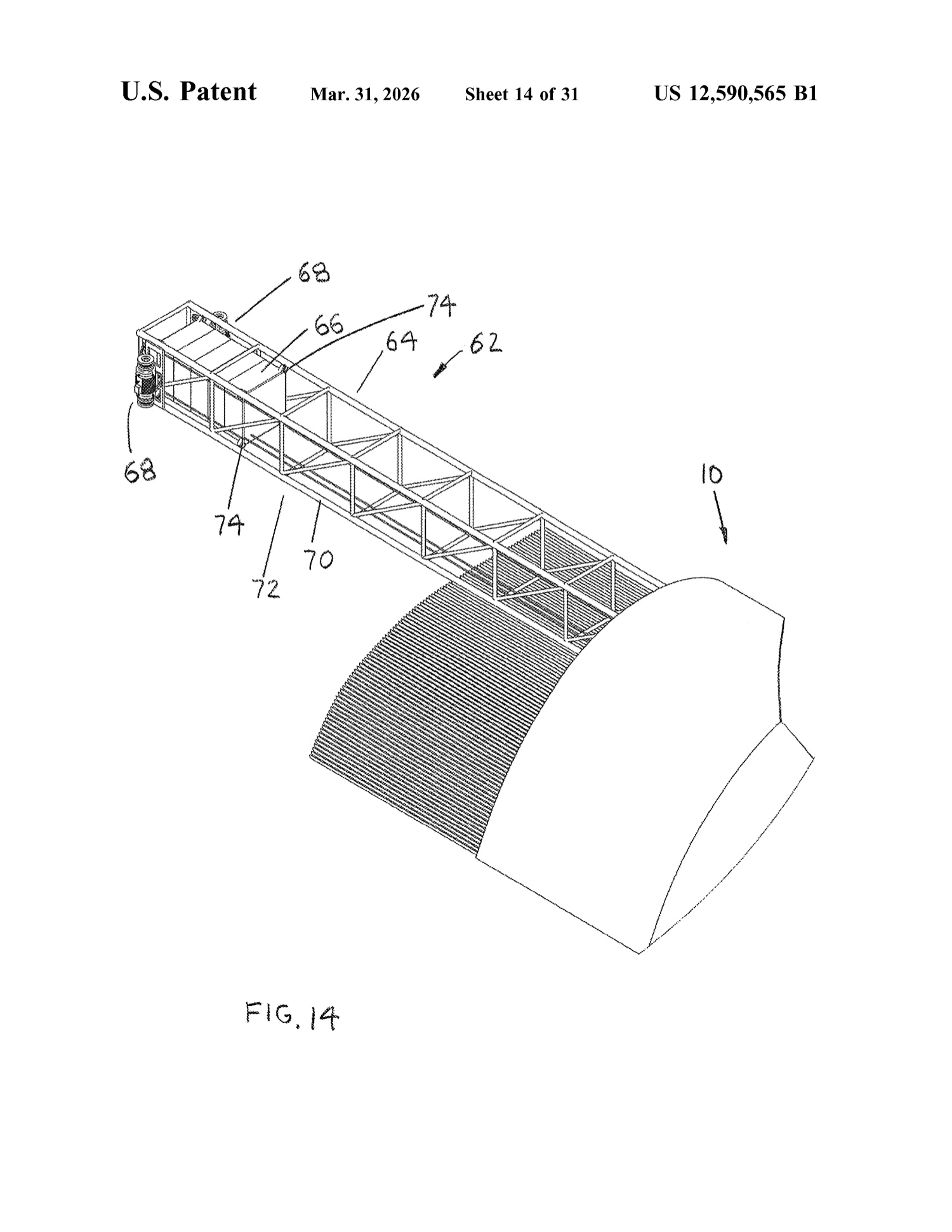
Fig.14 shows the internal lengthwise frame, rail structure, sliding mass and drive arrangement.
HEPS / 02Original design record
02Move mass. Measure the net effect.
Internal blade weight system
An internal frame, rail and drive arrangement changes the radial position of mass inside a modular blade. Our historical scale testing gives this work a starting point.
What we will establish
Actuator energy, complete energy balance, rotor balance, weight containment, loads and fatigue in a suitable carrier blade.
Development route
Joint development with a blade manufacturer and independent rotor test team.
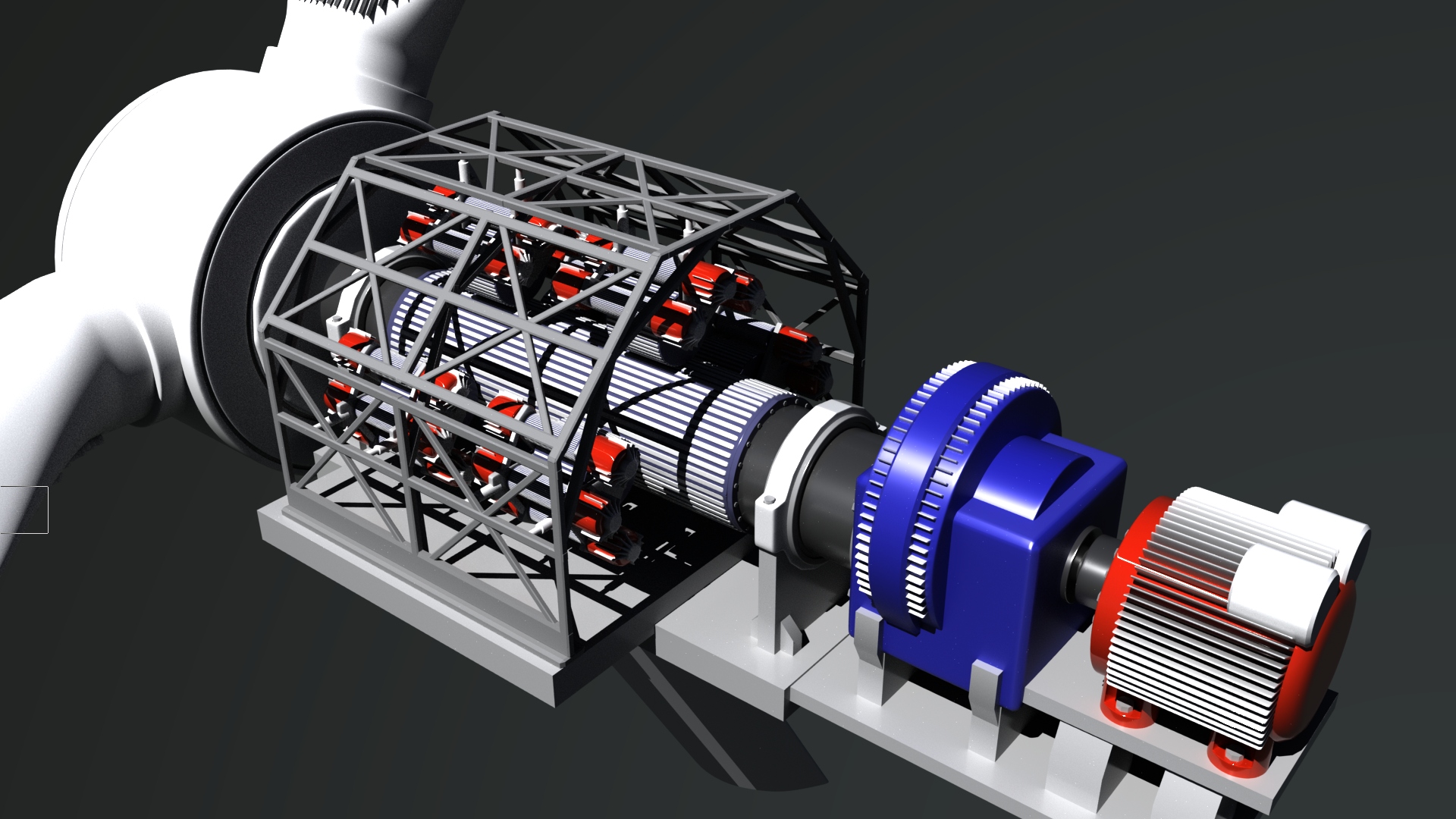
The main shaft connects through magnetic coupling and gearing to generator units. Controlled engagement is part of the adaptive-nacelle architecture.
HEPS / 03Original design record
03A different approach to conversion
Adaptive generator
Magnetic coupling and gearing connect the main shaft to multiple generator modules, with controlled engagement and cooling. The work focuses on conversion behavior across a range of operating conditions.
What we will establish
Torque-speed efficiency, auxiliary consumption, thermal behavior, controls and physical integration with the selected host turbine.
Development route
Bench development followed by a defined full-scale trial with generation and drivetrain partners.
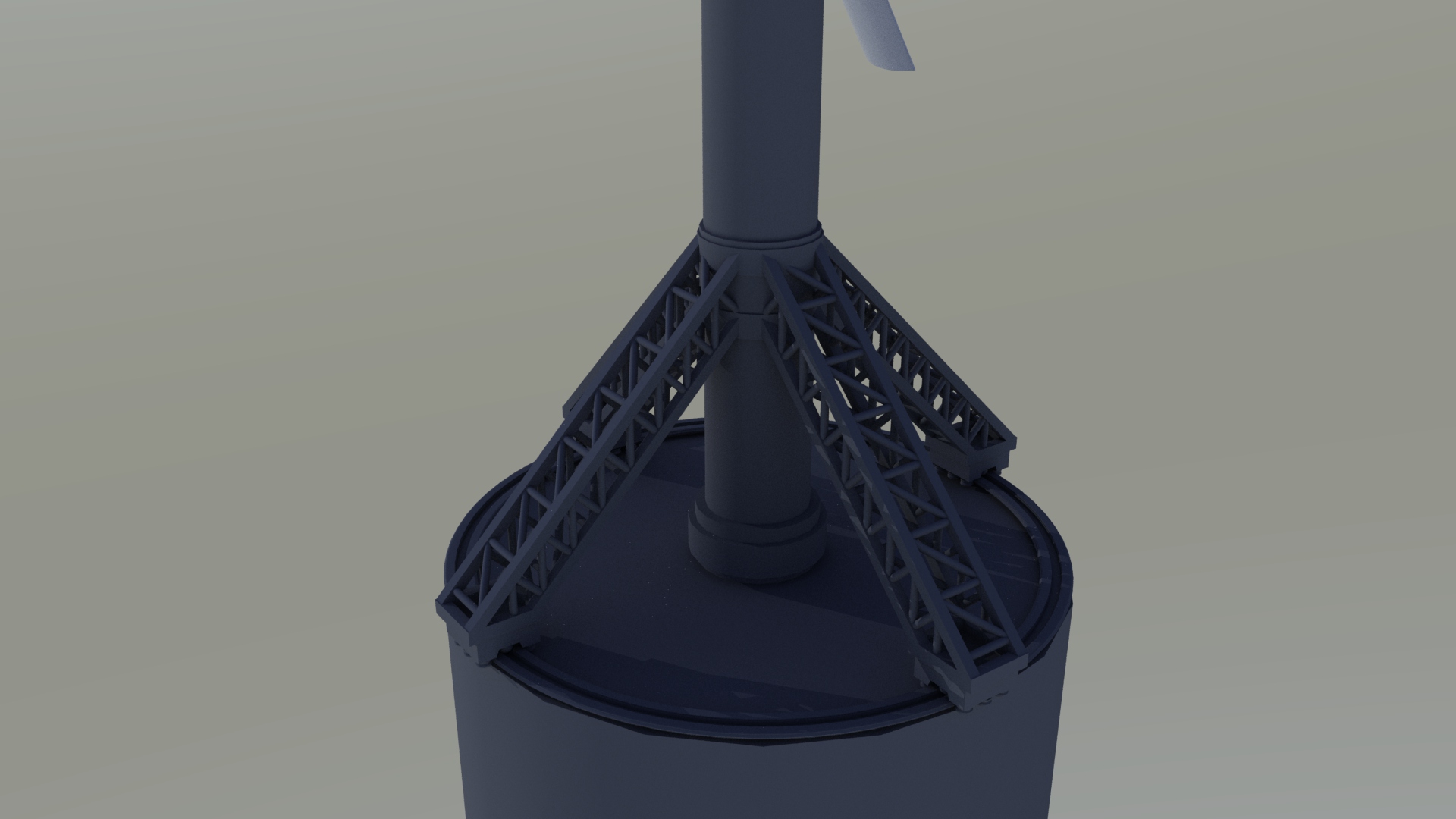
Original design reference04 / Rotating towerHEPS rotating tower render · support ring and braced baseOriginal ↗
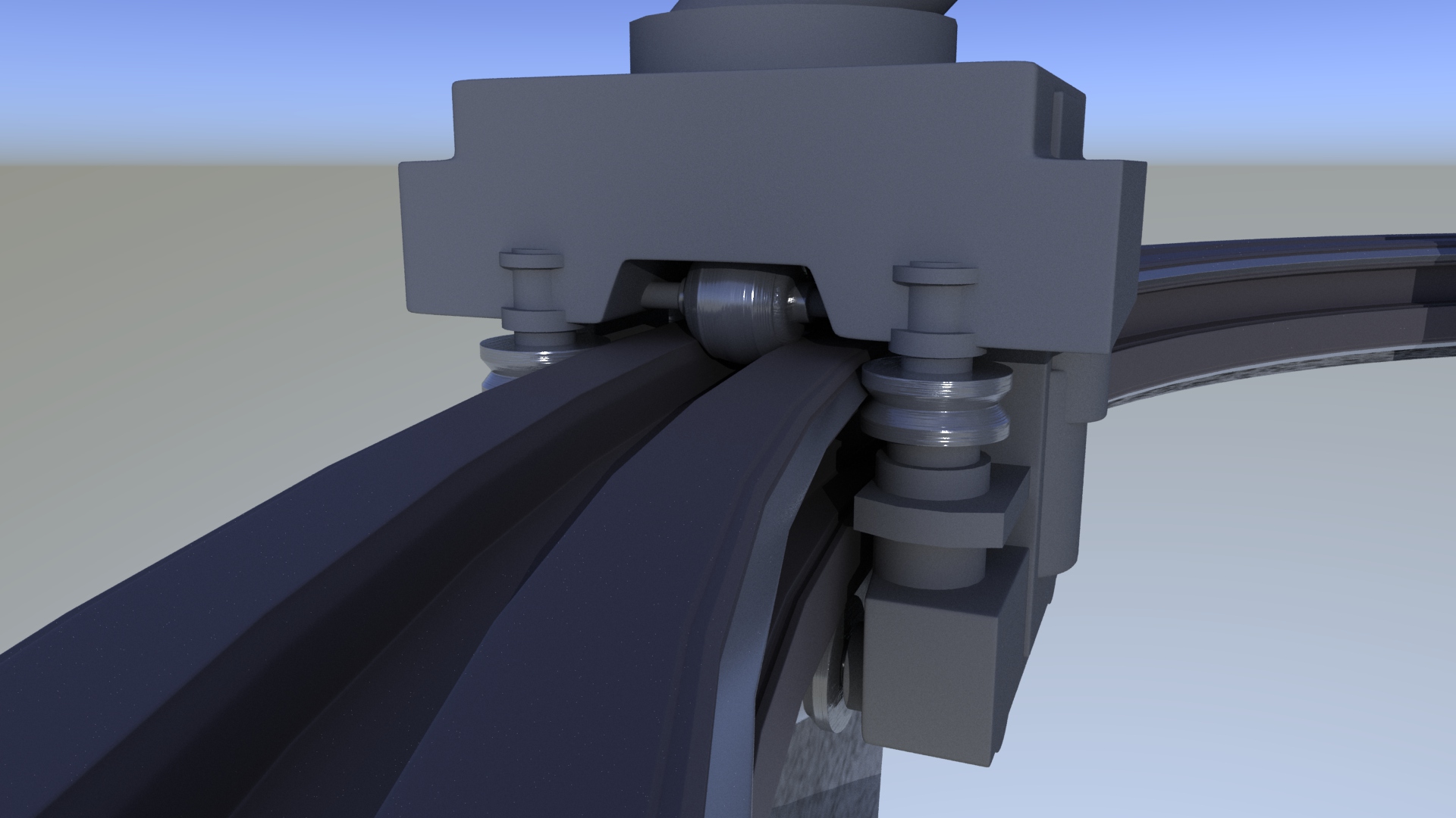
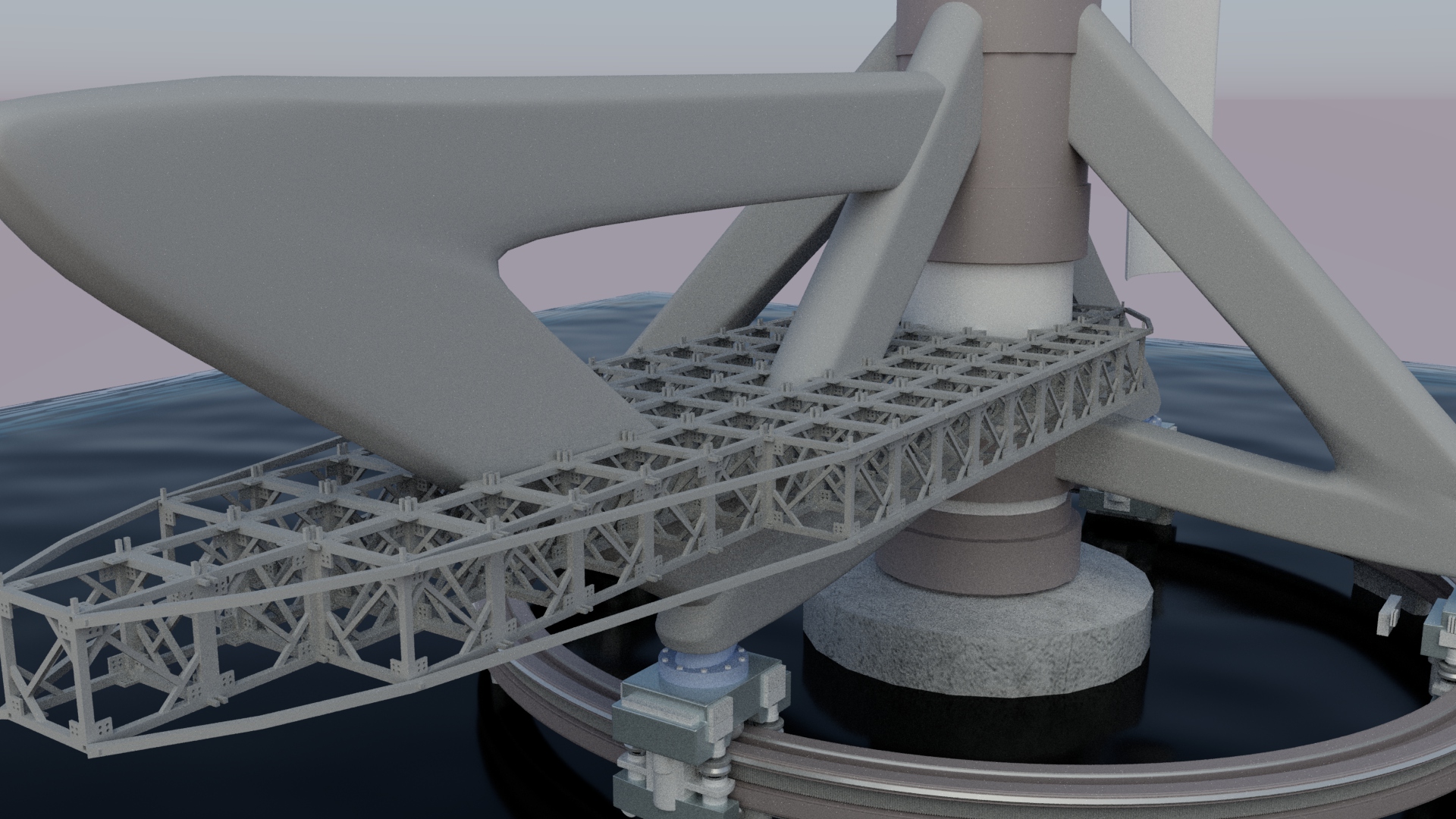
This source render shows the broad tower body, braced base and circular support rail. The detail renders below show the roller carriage and modular framing; the issued patent drawing remains available through the patent link.
HEPS / 04Original design record
04Yaw at the base
Rotating tower
The patented architecture uses a broad tower body, base support and roller-drive arrangements. The tower and nacelle yaw together rather than relying on conventional nacelle rotation.
What we will establish
Foundation and bearing design, structural and dynamic loads, fatigue, yaw power and lifecycle economics.
Development route
A dedicated structural development program before an integrated full-scale demonstration.
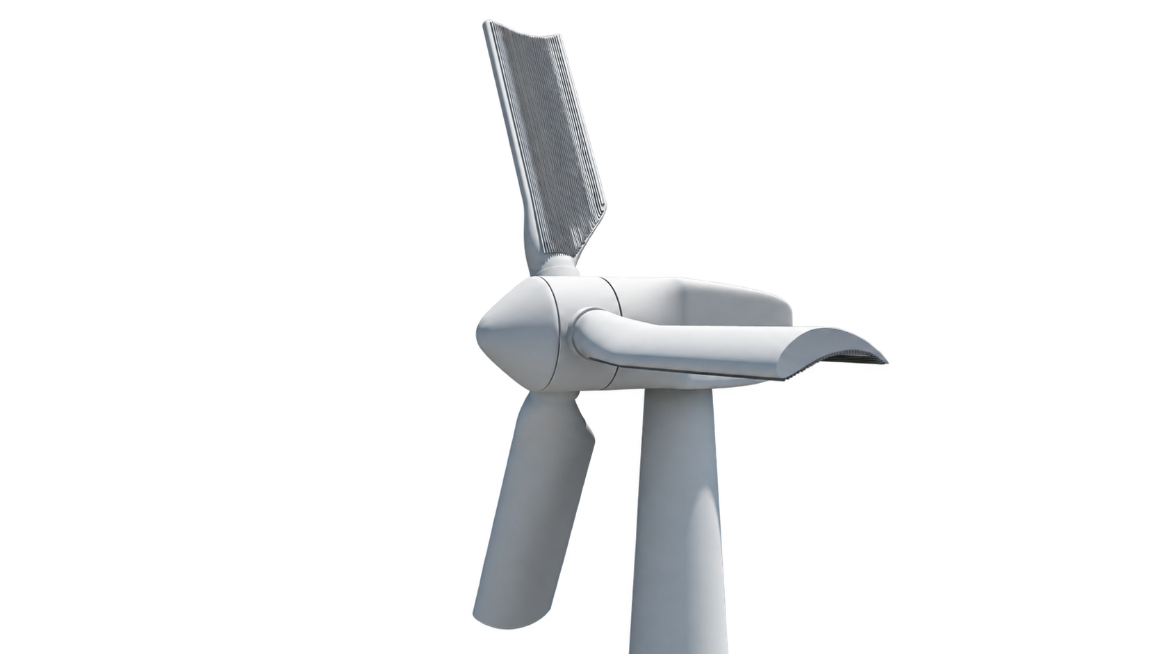
Original design reference05 / Integrated wind turbineHEPS turbine concept render · background removed for presentationOriginal ↗
This original perspective render connects the rotor and nacelle to the broad tower body. It illustrates the proposed system architecture.
HEPS / 05Original design record
05Connect the portfolio
Integrated wind turbine
Our longer-term objective combines the accepted blade, generator and tower technologies. The first full-scale program centers on a suitable existing 500 kW–2 MW turbine, while structural tracks may require separate hardware.
What we will establish
Coupled controls and loads, net electrical output, installation and maintenance economics, and acceptance of the complete system.
Development route
A staged engineering consortium. The 100 MW+ concept remains a research ambition, not a demonstrated capacity.
The original HEPS design animation explores the relationships within the generator architecture. It is concept animation, not footage of an operating commercial turbine.
Original patent drawings and HEPS design renders document mechanisms and proposed configurations. They do not establish fabrication dimensions, commercial performance or proven output gains.
Read the technology guides
Explore each concept in detail.
Start with a plain-language description, then inspect the mechanism, evidence and development questions.
HEPS blade fins are surface features proposed for the pressure side of a wind turbine blade. They are an aerodynamic concept within the HEPS portfolio. Original design renders and animations explain the arrangement; wind-tunnel and electrical-output tests must establish whether it provides a useful net benefit.
HEPS modular wind turbine blades use joined span sections beneath a smooth aerodynamic exterior. The proposed construction aims to support transport and assembly near the turbine site. The concept model shows ribs, spars, joints and pitch motion; transport dimensions, joint strength and fatigue life still require engineering.
The HEPS internal blade weight system proposes moving mass along guide rails inside a modular wind turbine blade. Repositioning the carriages changes the distribution of rotating mass. This architecture requires an HEPS rotating tower; any net electrical benefit must account for actuation energy, structural loads and losses.
The HEPS adaptive generator concept places movable generator modules around a magnet-lined main shaft in an open support frame. Actuators change the modules’ radial position to illustrate proposed engagement control. An elongated variant adds module banks; efficiency, magnetic clearances, cooling, control behavior and net output still need validation.
HEPS rotating tower concepts propose turning the complete tower and mounted equipment at a base bearing and rail-supported roller system. Cylindrical and symmetric biconvex forms use stacked structural modules. The architecture differs from conventional top-nacelle yaw; foundations, restraints, bearings and load capacity require structural validation.
The integrated HEPS wind turbine concept combines compatible modular blades, internal weights, adaptive generation and a rotating tower. The 100 MW research configuration adds a biconvex tower and elongated generator architecture. Its rating is a research target; the models and comparison calculator do not establish commercial or independently tested performance.
06
Inside the architecture
The details carry the design.
Original HEPS renders show the rotating support rail and structural framing.
04 / Roller and rail engagementHEPS tower render · roller carriage on the circular support railOriginal ↗04 / Structural framingHEPS tower render · modular framing and base bracing detailOriginal ↗
Concept renders from the HEPS design archive. Open the original files or inspect the issued drawings in the patent library.
The next phase / Join the work
Bring your expertise. Build the next step.
Wind asset owners. Engineering and test teams. Industrial investors. Development partners.